I built a small audio amplifier around an LM386. It worked as intended and helped me understand first-principles from building electronics. Then I decided I wanted to listen to music in my car with it, and real-world constraints showed me one of the reasons hardware and software are different. The requirement changed underneath it.
This is what I learned pulling that thread, including the part where I realized the expensive fix wasn’t the efficient one.
The original board
A mono LM386 amp with a 3.5mm aux input, a jack input, a passive stereo-to-mono mixer, a volume pot, and an output Zobel network. Power came in through a resettable fuse, a switch, and a P-channel MOSFET for reverse-polarity protection.
For a desk speaker this is a good design. The LM386 is cheap, forgiving, and needs almost no support components. I had it playing music on the bench and I was happy with it.
I also learn the importance of the Zobel network, making the sound much cleaner.
The requirement that broke it
A moving car cabin sits at roughly 65 to 75 dB of road, engine and wind noise. That is the number that matters, and it is the number I had not thought about.
The LM386 delivers well under a watt. Sound pressure works out as:
SPL = sensitivity + 10 × log10(watts) − distance losses
At 0.5 W, the power term is 10 × log10(0.5) = −3 dB. With a reasonably efficient 88 dB/W speaker, that puts the ceiling at 85 dB at one metre.
Here is the thing: 85 dB is above 65–75 dB of cabin noise. On paper the LM386 is not absurd. It is not twenty decibels short. So why does everyone who tries this come away disappointed?
Headroom, not volume
Because 85 dB is the maximum the chip can produce, and music is not a constant tone.
Music has a crest factor of roughly 10 to 15 dB, meaning its peaks run ten to thirty times the average power. To get 85 dB of clean average level, the amplifier must be capable of 95 to 100 dB peaks. The LM386 cannot, so every transient hits the ceiling and clips.
The result does not sound quiet so much as harsh, compressed and tiring. It also sounds thin, because clipping bites hardest on the bass transients that carry most of the energy.
That reframing was the moment the decision became obvious. The problem was never that the LM386 produced no sound. It was that its ceiling sat at the level I needed instead of comfortably above it, leaving nothing for the peaks that music actually consists of.
No number of tuning fixes this. I could raise the supply voltage and pick a better speaker, and both would help, but the output ceiling is architectural. It is worth saying plainly that gain and power are not the same thing: my board was set to the LM386’s maximum gain of 200, and turning that down improved the noise floor while changing the available output power not at all.
The replacement
I moved to a TDA7297: a dual bridge amplifier, about 7 W per channel at 12 V into 8 Ω. Note it is class-AB, not class-D, which matters later.
Same formula, new power term: 10 × log10(7) = +8.5 dB. With the same 88 dB/W speaker that is 96.5 dB at one metre, and two speakers playing together add roughly another 3 dB.
Apply the headroom test that the LM386 failed:

The part I did not expect
The new chip needed fewer external components, not more.
The TDA7297’s outputs are bridged, so the speaker connects directly between OUT+ and OUT with no output coupling capacitor. That deleted a 470 µF part and took the bass roll-off it was causing with it. Gain is fixed internally at about 32 dB, so the gain network went. The datasheet advertises no Boucherot cells and no SVR capacitor, so the Zobel network and the supply-rejection cap went too.
And because it is stereo, the passive mono mixer: four resistors that existed purely to work around the LM386 being a single-channel part became deletable.
I ended up with a simpler schematic that does more.
What it actually cost
The electrical design was the easy part. The consequences were not.
Heat. Class-AB at this power dissipates real wattage. Working backwards from a 60 °C car interior and a derated junction temperature, I needed a heatsink around 4 °C/W. The standard PCB-mount TO-220 heatsinks in that family are 8 to 14 °C/W — the largest one is still half what the worst case wants. It copes fine at normal listening levels, where dissipation is a few watts, but it will not support sustained full output on a hot day. The chip’s own operating range tops out at 70 °C, so the thermal envelope turned out to be a tighter constraint than anything electrical.
Current. Supply draw went from milliamps to roughly 2 to 2.5 A continuous with 4 A peaks. That single change cascaded:
- The resettable fuse needed resizing, and PTC fuses derate with ambient temperature. Holding 3 A on the bench may hold closer to 2 A at 60 °C, which is exactly the nuisance-trip scenario in a car. Its 105 mΩ resistance also costs a quarter of a volt at operating current.
- The protection MOSFET moved from a small surface-mount package to TO-220. A SOT-23 part with 150 mΩ on-resistance would dissipate about a watt at 2.5 A, in a package that can shed maybe 0.3 W. It would cook itself.
- Trace widths split into classes: 0.25 mm for signal, 0.75 mm and up for the supply and speaker outputs, and a ground plane instead of routed returns.
- AA cells stopped being viable as a power source entirely.
Complexity. An eight-pin DIP became a fifteen-lead Multiwatt package, with all the pinout verification that implies. On a bridged amplifier, wiring an output pair to the wrong pins destroys the chip on first power-up, so that verification is not optional.
The uncomfortable arithmetic
Fourteen times the output power bought me about 11.5 dB of ceiling. Ten decibels is the conventional definition of “twice as loud”, so this was a real, perceptible, worthwhile gain. It was the difference between an amplifier that clips on every transient and one that plays cleanly.
But look at what else was available for that 10 dB:
| Change | Gain | Cost |
| LM386 → TDA7297 | ~11.5 dB | full redesign, heatsink, new power chain |
| 84 dB/W → 92 dB/W speaker | 8 dB | a different part number |
| Sealed enclosure vs bare driver | several dB, plus most of the bass | a box I was building anyway |
| Second speaker | 3 dB | already implied by going stereo |
The electrical redesign was the most expensive route to loudness available to me. Speaker sensitivity (how efficiently a driver turns watts into sound, usually specified in dB at 1 W and 1 m) spans roughly 84 to 92 dB across ordinary drivers. That eight-decibel spread is worth more than quadrupling amplifier power, and it costs nothing, because I was buying a speaker either way.
A bare driver also cancels its own bass: the rear wave meets the front wave and they subtract. The same speaker in a sealed box sounds dramatically fuller for the price of some wood.
So the honest priority order for making something louder is enclosure, then speaker, then amplifier. I did them in reverse.
Was it worth it
Yes, but not for the reason I started.
The redesign was genuinely necessary. The LM386’s ceiling was too low and no speaker choice fixes a clipping amplifier. I would make the same call again. But if I had understood the arithmetic first, I would have specified the speaker and the enclosure before touching the circuit, and I might have arrived at a smaller, cooler, cheaper board that was loud enough.
The consolation is that the 10 dB was never the only output. Along the way I learned thermal budgeting, net classes and ground planes, multi-unit schematic symbols, the difference between a symbol pin and a footprint pad, PTC temperature derating, and why a bridged output must never have a grounded speaker terminal. None of that came from the decibels.
The thing I would tell anyone starting the same project: the satisfying engineering answer and the efficient answer are often not the same answer, and it is worth knowing which one you are chasing.
This is the final 3d model of the board
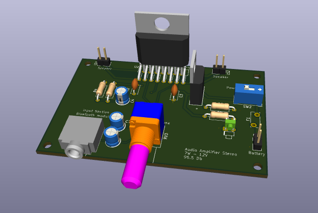
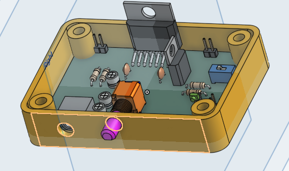
I’m currently working on finishing the case for the board using Onshape. Ironically, the enclosure I initially treated as an afterthought may end up contributing almost as much to the final listening experience as the amplifier redesign itself.
 Diogo Gonçalves
Leave a comment