Projects
This page is a running log of electronics projects I’m building and refining over time. Entries include design notes, implementation details, and what I’m currently testing or planning next.
PCB Humidity Sensor for Plants
In Progress
I decided to come back to my roots (no pun intended) and start working on small eletronic projects. I’ve done my Bachelor and Master degrees in Eletrical Engineer and Computer Science, but besides some small teaching, i’ve always worked as a software engineer. Going back to this, i decided to follow some projects in github of people working on humidity soil sensors, and work on a end to end project, until possible create something that is commercially viable at least. Not that my intention is to make money with this, but i believe it’s a good way to focus on quality and on doing something where quality and cost are taking into account.
Fortunatly, i had some old material from when i was teaching, and i found an arduino uno, a breadboard and a several eletronic components that allow me to start testing some principles.
I also start buying a few equipament that will be necessary for this and further projects: multimeter, soldering station and storage for my eletrical components. Further investment will be required, and i intent to create a full eletronic workstation bench at my house. But for now, this is sufficient.
I worked on a good way to simply test the sensor, and i end up with this schematic:
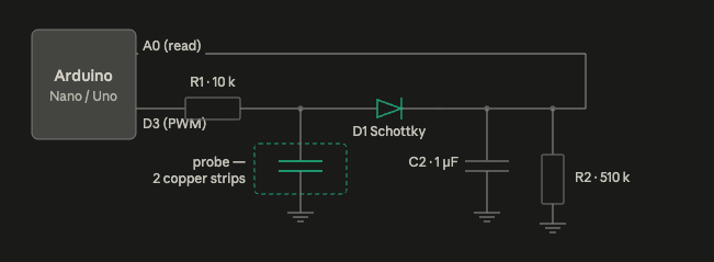
We are using the analog port in the Arduino to read the sensor values. and our D3 port is basically sending 5v pulses to the system to take a measure each time.
R1 is just a protection against current peaks.
Our probe is the actual sensor. it basically operates as a capacitor, where the soil is the dieletric. If humidity goes up, the dieletric constant increases, making the capacitor be able to store more charge.
The capacitor C2 smooths the incoming pulses and stores charge, while R2 slowly discharges C2. Together they form a low-pass filter that converts rapid changes into a stable voltage that can be measured by A0.
The Schottky diode is protection the circuit when C2 is discharging, making sure there is no current going in the wrong direction.
Mounting this in the breadboard for testing and i just confirm that it works.
This was the easy part. but it confirms i can do something similar in a real PCB.
It’s time to switch to KiCad and turn this into something more sophisticated
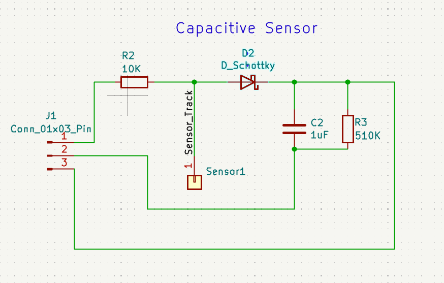
I decided to start small, since this will be my first pcb board. Instead of the full circuit, i decided to just recreate the sensor to test it, and to begin working on soldering skills. This was my schematic.
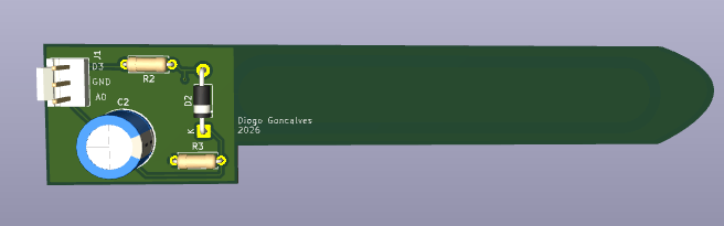
And this is the 3D visualization of the board.
Current focus
I’m iterating on the first revision of the PCB, concentrating on stable analog readings in a humid, corrosive environment. I’m also validating component choices to balance accuracy, lifetime, and cost.
- Refining electrode geometry for consistent moisture response
- Testing different protection strategies against soil corrosion
- Designing the analog front-end for low-noise, repeatable readings
- Planning the interface to a microcontroller for data logging
Design notes
This is still an early-stage board, so the emphasis is on learning from each prototype rather than optimizing for production. I’m logging:
- How trace routing and ground layout impact measurement stability
- Drift over time when the sensor stays in soil for days or weeks
- Calibration approaches that stay valid across different soil types
- Assembly notes for hand-soldering vs. small-batch assembly
Once the readings are consistent enough, the next step will be integrating temperature compensation and defining a simple protocol for external controllers.
Next updates planned
- Documenting the first PCB revision, including schematic and layout rationale
- Capturing measurement data across different soil types and watering cycles
- Adding photos and notes from early breadboard and probe tests
Other Projects
-
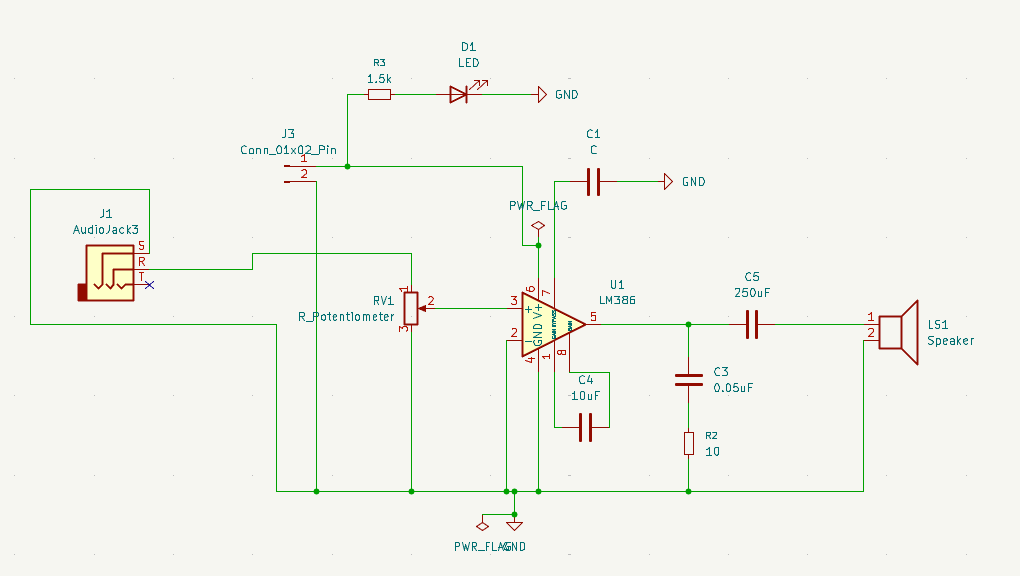
Building a Low-Power Audio Amplifier
In my quest to learn electronics, i decided to build a low-power audio amplifier. It’s a circuit that teaches several important concepts, and it can also be reused as a…
 Diogo Gonçalves