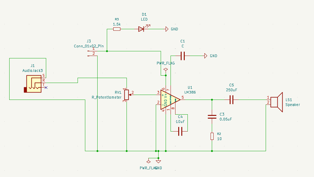
In my quest to learn electronics, i decided to build a low-power audio amplifier. It’s a circuit that teaches several important concepts, and it can also be reused as a module in future projects I want build, such as an FM radio.
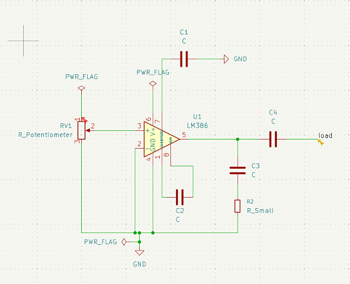
After a few iterations, I created this schematic for it, based on the datasheet provided by Texas Instruments and some personal tweaks.
The integrated circuit I’m using is the LM386N, which serves as the core of the circuit and acts as a low-voltage audio amplifier. I’m powering it with 5V, and it receives the signal from a 3.5mm audio jack.
What I like about this project is that it forces you to understand why capacitors are used in different ways.
Some capacitors are connected in parallel with the power supply. For example, C1 helps stabilize the supply voltage by filtering disturbances and noise. C3, which is part of the zobel network, contributes to stability, although in a different way. Together with the resistor, it helps compensate for the speaker’s inductive behavior and improves amplifier stability at higher frequencies.
Other capacitors are connected in series with the signal path. C4 is there specifically to block DC. It only allows variations to pass to the speaker, and therefore the speaker only detects the audio. Capacitors in series act as an open circuit in DC.
The potentiometer controls the volume by attenuating the input signal before it reaches the amplifier. Currently I don’t have a potentiometer, so I’m using two resistors to create a voltage divider for my test.
The C2 is reacting to the internal feedback of the circuit to increase the gain of the amplifier. Without it, the gain is around 20x. Adding it increases the gain to approximately 200x.
Overall, this is a relatively simple circuit, but it introduces many important concepts:
- Signal coupling
- Power supply decoupling
- Feedback and gain
- Audio amplification
- Basic analog circuit design
More importantly, it creates a reusable building block that can be integrated into many future projects. The final design in KiCad is shown below
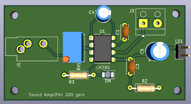
I’ve already ordered five boards from JLCPCB and am now waiting for their arrivel. In the meanwhile, I decided to test and implemented the circuit in a breadboard. After a few attempts I managed to make it work.
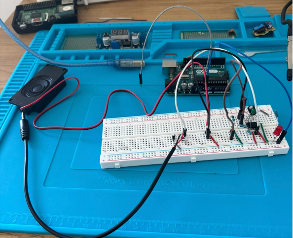
This is the final schematic I applied for the breadboard. Now I just have to wait for the pcb board, and will start focusing on the RF circuit part to mount my radio.
 Diogo Gonçalves
Leave a comment